Cleanrooms consume large amounts of energy compared with non-classified rooms; scientific literature and experience in the field show that cleanrooms use up to 25.3 times more energy (1.25kW/sqm vs. 0.06kW/sqm). The energy requirement of HVAC systems usually amounts to 50-75% of electricity consumption in a clean production space due to the high airflow rates needed for particular ISO classes.
This consumption directly relates to the design of a cleanroom and it must be taken into account to achieving an optimised design. For example, the energy footprint is where high energy consumption leads to high carbon dioxide (CO2) footprint.
The importance of manufacturing cost-efficiently is another factor. Furthermore, there are markets where cleanroom technology is not even available due to high life cycle costs (LCC).
This article talks about LCC instead of total cost of ownership (TCC) due to the fact that the demolition of the cleanroom and the materials that will be used are considered at the design phase. However, the TCO will at all times be an important component of LCC.
By understanding what leads to high energy usage, five key aspects have been determined to help reduce energy consumption and lower the energy footprint in modular pre-engineered cleanroom design.
Airtightness
Air in a cleanroom is costly if not one of the most expensive types of air. Historically, very little attention used to be paid to the airtightness of a cleanroom, but today, this is a factor greatly considered during design to minimise air leakage and optimise efficiency.
The Association of Contamination Control Netherlands (VCCN) Guideline 10 discusses airtightness. Before it, airtightness was indefinable, with no consistent method. For years, the passive house standard has been applied, but there is little relevance to this building standard upon cleanroom applications.
The VCCN 10 guideline brings uniformity in the design of airtightness and it describes the classification of the cleanroom shell’s air permeability (the walls, the ceiling and the floor). The guideline should, therefore, be put forward for the design phase of the user requirement specification (URS). Airtightness is defined as the resistance to inward or outward air leakage through unintentional leakage points or areas in the building envelope. The terms ‘airtightness’ and ‘air permeability’ are often used as synonyms, but they are in fact, opposites.
Airtightness in VCCN’s Guideline 10 refers to the degree of restriction of uncontrolled airflow through the cleanroom shell.
Air permeability refers to the rate of airflow through the building shell when there is different air pressure on either surface of the shell.
Classification by leakage class
An overview of the leakage classification is detailed in Table 1, ranging from L00 up to L5. What does this mean? Guideline 10 defines several leakage classes, classified by the maximum amount of air leakage per square metre building shell surface; this is known as the leak factor.
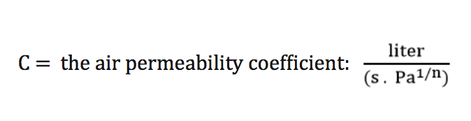
Applying the leak factor in the formula here results in a maximum amount of uncontrolled airflow per square metre at various pressure differences. Table 1 (see below) shows the importance of the leakage classification for design.
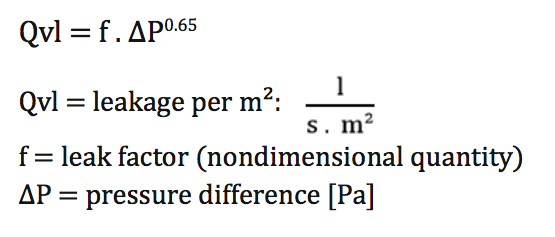
Using the formula aiming for a leakage class of at least L3, with a pressure difference of 50Pa, means an air leakage of 0.0381 litres per second per square metre (l/sm²). With the same pressure difference, leakage class L1 comes at an air leakage of 0.3433 l/sm², nearly tenfold.
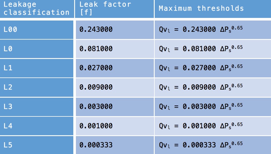
Table 1: Overview of leakage classes, classified by the maximum amount of uncontrolled airflow per m2 building shell surface (source: VCCN)
There is a strong relationship between the volume of the cleanroom and the potentially feasible leak-tightness factor. The smaller the room, the more difficult it is to obtain a high leak-tightness factor. This is not necessarily from an architectural point of view, rather from the limitations of regulation technology. Nevertheless, new algorithms beyond VAV (variable air volume) allow designers to engineer the highest leak-tightness (smallest leak factor) even with very small cleanroom dimensions, e.g. 50 m³.
Surprisingly, leakages are created deliberately in smaller cleanrooms, and specifically to allow pressure regulation as a result of a failing up-to-date control system.
Pre-engineering modular cleanrooms lead to fewer leakages since design engineers have already thought of everything, in contrast to having to improvise on the construction site, which results in a lot of trial and error.
Controlled filtration
From a pre-engineered and modular cleanrooms perspective, dynamically controlled filtration (DCF) flow rates have a tremendous impact on energy consumption. ISO Class 7 cleanrooms usually have a rate of 25 air changes. With a particle counting system, it would be evident that this is not always necessary. For example, with little contamination in the room (low demand for filtration) and a continuous particle monitoring system, an air change rate of 10 is tolerable. But, a higher air change rate would undoubtedly be required for more contamination risks, potentially due to process environments or cleanroom users who don’t keep in mind their cleanroom dress code. This degree of filtration controllability in different circumstances is what DCF is about.
By looking at a PAL (personnel airlock), we see that the pre-defined recovery time is an important value in cleanroom design. If we apply DCF when entering the PAL, ventilation flow can temporarily be increased to reduce the recovery time, saving time for the cleanroom user.
The formula used for DCF is the following: N = - 2.3 . 1/t. log10 (C/C1)
N = decay rate of particles = air change rate at the measuring location
t = time of decay
C = airborne concentration of particles after a given decay time
C1 = initial airborne concentration of particles
The formula above shows that the recovery time depends on the air change rate. The time value often used in GMP environments is 15 minutes.
C = 3520
C1= 352.000
N = - 2.3 . 1/15 . log10 (3520/352.000) = 0.306 AC/min = 18.36 AC/hour
So, if we reduce decay time to five minutes, an air change rate of 55 will be needed. In conclusion, dynamic regulation of the air change rate has a positive effect on the recovery time, and not only by entering a PAL but to all zones inside a cleanroom area.
The modular interpretation of cleanroom engineering allows configuration of the necessary building blocks with dynamically controlled ventilation flow rates.
Air change effectiveness
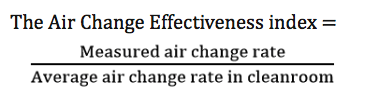
An important value in traditional cleanroom design is the air change effectiveness (ACE). ACE indexes, however, are often underestimated despite being reported extensively in the scientific literature such as Whyte et al (2014).
An essential design parameter is the effect of an air diffuser on the airflow. When sketching a non-unidirectional airflow (non-UDAF) cleanroom, designers have to decide how much filtered air should be supplied to achieve a required cleanroom classification as specified in ISO 14644-1 (2015), Annex 1 (cGMP). In practice, the decision on the air change rate in a classified room used to be somewhat standardised and based on experience and assumptions, not on an analytical model.
Conversely, ABN engineers have noticed increasing air change rates in higher cleanroom classifications. This trend has lead to a number of questions:
- To what degree are the air changes effective?
- How well is the air distributed in a cleanroom?
- Have professionals been thinking about the volume of air that needs to be blown into the cleanroom, but not about the distribution of the air in that room?
By focusing on these questions, the ACE has become a decisive topic in modular cleanroom design.
The ACE can sometimes be confused with ventilation effectiveness, which describes the ability of an air distribution system to eliminate internally generated pollutants. It is common practice for cleanrooms to use ventilation systems with high airflow rates to control indoor contaminants. Unfortunately, those systems are often more than needed and energy intensive.
Scientific literature has shown that Eulerian and Lagrangian numerical methods, as well as computational fluid dynamics (CFD), have been applied to examine airflow fields in non-UDAF cleanrooms. The knowledge indicates that many cleanrooms have excessive airflow rates, leading to greater TCC including high capital, running, and energy cost. Poor air mixing is not only related to the correct positioning of the air inlet points and type of air diffusers. In many cases, the location and quantity of wall return points are even more important. Correct positioning of the wall return air grills allows an increase of ACE with a lower air supply rate, resulting in a more energy efficient cleanroom.
The determined air change rate at a location is obtained by measuring the decay rate of test particles. The following formula, relating to the DCF, can be applied:
N = - 1/t in C/C1
N = decay rate of particles = air change rate at the measuring location
t = time of decay
C = airborne concentration of particles after a given decay time
C1 = initial airborne concentration of particles
If the cleanroom is perfectly mixed, the ACE index will have the value of 1 at all locations. In the situation that the ACE index is a higher value than 1, more clean HEPA filtered air than average will reach the test location and the cleanliness classification will be better. The advantage of pre-engineered modular cleanroom design compared to a conventional one is the ease of making adjustments without major modifications. For example, process machines move over around time, and thereby heavily influence the airflow and its effectiveness at cleaning the air. How the ACE shows a strong relationship with CFD will be clarified below.
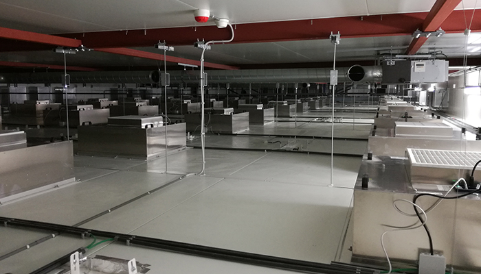
For this cleanroom in the Netherlands, the VIX algorithm was implemented to gain energy-efficient air purification. In this case, over 80 HEPA filter fan units were installed
Computational fluid dynamics
When learning about forces that drive energy efficiency in modular pre-engineered cleanroom design, CFD must be mentioned. The concept linked to digital twins: the creation of a digital mirror environment that can digitally simulate scenarios to examine how an event would turn out in reality. This refers to what has been said about changing setups in cleanrooms, where for example process machines might be changed from one location to another over a certain period of time.
Real-time simulation and artificial intelligence can be used to enhance the design of the cleanroom or process by evaluating alternative designs. Such evaluation prior to building leads to optimised airflow management and therefore energy management.
CFD software is used to model and to predict fluid airflows, both are critical in order to optimise energy efficiency. This dynamic simulation is typically used to optimise thermal performance of cleanrooms under various conditions. It is also used to analyse complex 3D cooling flows and to conjugate heat transfers in the airflow. With CFD as part of a digital twin, airflows can be simulated optimally within these changing setups. An efficient airflow (not too low or high) will be a clear advantage from digital twins.
The Internet of Things provides the potential for a transformational journey, in which a simulated model of the cleanroom is tied through the internet to sensors and to actuators controlling its operation. The result is a digital twin of the physical product or process that can be used to analyse and diagnose its operation and to optimise its performance and maintenance in real time.
The simulation-based digital twin incorporates the physical process, the simulation models and the connections that facilitate communications between the two.
The applications of digital twins are :
- Energy savings through perfect CFD simulation to achieve the required cleanroom classification with minimal air change rates
- The lowest energy consumption by identifying the ideal period of maintenance (predictive maintenance)
- Industry 4.0-ready cleanroom design to capture data in order to transform data into wisdom through machine learning
Decentral ventilation control
In cleanroom design, we can distinguish two types of ventilation control: central ventilation control (CVC) and decentral ventilation control (DVC). CVC is characterised by its central air handling unit (AHU) and its limitations in modularity, controllability and energy efficiency due to high-pressure resistance in ducts that must be overcome.
With DVCs, however, there is a pressure drop as we see with filter fan units (FFUs). This is because FFUs do not have to compensate for additional pressure losses in ducts. And this is a decisive factor for energy optimisation. An additional advantage of DVC is the ease of applying a night setback function to specific zones while not others at the same time. In CVC is it is ‘all-or-nothing’.
DVC is strongly related to DCF, discussed earlier, and allows specific zones to have higher air change rates compared to CVCs.
The concept of DVC fits perfectly with modular cleanroom design. The potential for energy saving here is tremendous. However, an extra point of attention arises. For system engineering in modular cleanroom, DVC system design greatly relates to a decoupled design, which, unlike a coupled one, allows partial decoupling in case of failure of a part of the system.
The axiomatic design theory clarifies coupled and uncoupled design based on functional requirements (FRs) and design parameters (DPs). The illustration below shows the uncoupled design matrix:
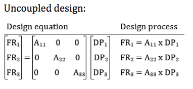
By implementing modular and pre-engineered cleanroom design, decoupling design systems enter the market leading to a substantial increase in reliability.
N.B. This article is featured in the February 2019 issue of Cleanroom Technology. The digital edition is available online.