Following on from the guide to designing a cleanroom monitoring system, published in the September issue of Cleanroom Technology, this article is set up to cover the critical aspects involved in the installation of a monitoring system under the validation steps as per the guidelines of the ISPE GAMP5.
GAMP is an acronym for Good Automated Manufacturing Practice, and it is both a technical subcommittee of the International Society for Pharmaceutical Engineering (ISPE) and a set of guidelines for manufacturers and users of automated systems in the pharmaceutical industry for a risk-based approach to computer system validation.
Volume 5 of the GAMP (GAMP5) was published in 2008 by the ISPE task team alongside subject matter experts from field and steering committees from various countries.
The document's categorisation assists in selecting appropriate life cycle activities and documentation from category 1 “infrastructure software” up to category 5 “custom applications”. Moreover, the system categorisation helps guide the efficient writing of documentation, including specifications, test scripts and everything in between.
The table below gives more details about the categories and their intended use.
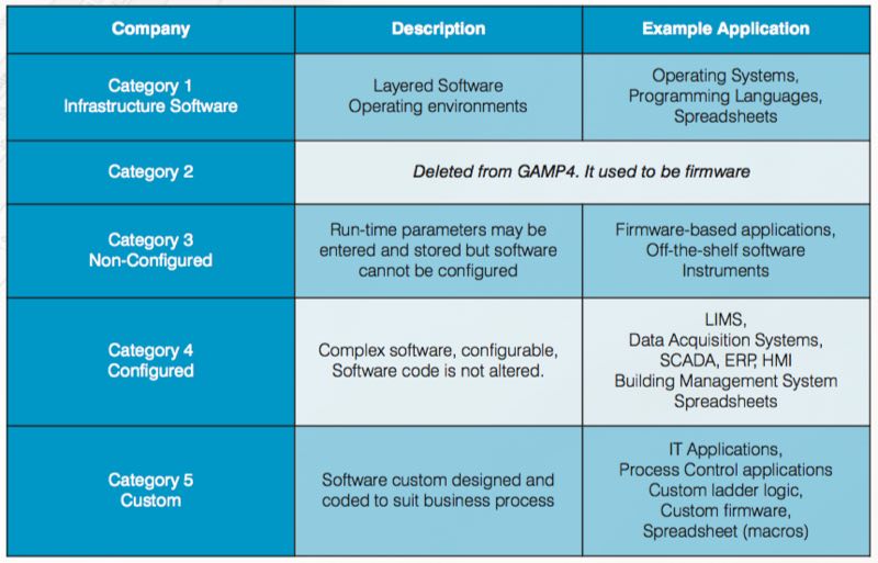
When coupled with risk assessment and supplier assessment, categorisation can be part of an effective quality risk management approach. The categories are useful when applied in conjunction with other risk management tools, and with consideration of complexity and size of the system. As per categorisation, complexity and risk increased, as shown in the sequence below:
Custom (Category 5) > Configured (Category 4) > Non-configured (Category 3) > Infrastructure (Category 1)
When it comes to validation, two approaches are very critical: the risk-based and life cycle approach. It’s not because they are in fashion in today's cleanroom markets; both really serve for appropriate system design and implementation.
The life cycle approach
Because the entire system lives as a concept, parameters, estimates and/or requirements are changing as the system lives. That’s why there is no straight line from A to Z for computerised system validation. The life cycle approach is also described in GAMP5, as shown in Figure 1 (see next page).
The life cycle for any system consists of four major phases: concept, project, operation, and retirement. As per GAMP5, suppliers of products and services should be involved as appropriate throughout the life cycle. It may be suitable to delegate many of the described activities to suppliers, subject to satisfactory supplier assessment and control measures.
The risk-based approach
Appropriate risk management processes should be followed throughout the life cycle to manage identified risks and to determine the rigour and extent of the activities required at each phase of the life cycle. Figure 1 also shows the typical use of risk-based decision-making throughout the life cycle.
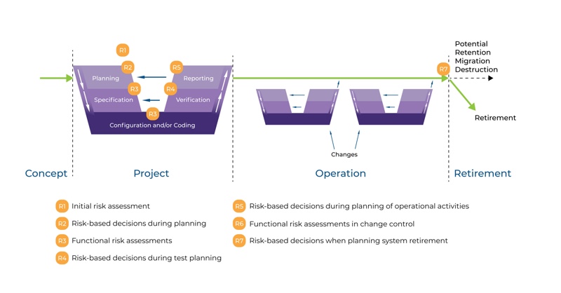
Figure 1: Life Cycle Approach
When talking about monitoring software, these are all configured systems (category 4) and even custom systems (category 5). These platforms feature complex structures with data modules, programmable logic controllers with custom ladder logics and custom firmware to meet client’s specific requirements.
To be able to apply proper GAMP5 requirements, a risk-based approach for a custom application should be maintained. There are two stages here: initial risk assessment even before forming the user requirement specification (URS) and functional risk assessment at the stages of specification such as function, design, and module specifications.
For the initial risk assessment, consider the following points:
- What are the overall risks to the business?
- Determine the system GxP
- What is the overall impact of the system?
- Are more detailed risk assessments required?
For the functional risk assessment, identify and define the following points:
- Identify risks to specific processes
- Identify risks to specific functions
- Define controls and reduce risk
- Iterate these step if necessary
As you can see in Figure 1, the project phase covers several activities from planning to reporting. The specification steps indicated on the right-hand side meet the verification steps on the left-hand side. The graphic is known as the GAMP5 V scheme.
The GAMP5 V scheme
The GAMP5 V scheme summarises all specification and testing activities. Figure 1 shows specification steps on the right-hand side and testing, qualification and verification steps on the left-hand side. Each level on the right-hand side also verifies the same level specification steps on the left. Figure 2 summarises the steps for online monitoring systems as category 5 custom application from validation planning to validation reporting.
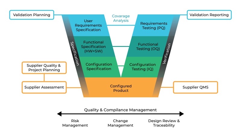
GAMP5 V Scheme Approach for a custom application (Cat 5)
As you can see, the most critical step, from category 1 to category 5, is the first step: user requirement specification. Without a proper URS defined by the customer’s multidisciplinary steering committee, the online monitoring system installation and validation will be limited by the supplier's knowledge, effectiveness of their quality management system (QMS), product capacity and project management abilities.
Most of the applications on viable and non-viable monitoring systems are limited and do not completely satisfy the needs due to lack of proper URS.
User requirement specification (URS)
As a regulated organisation, pharmaceuticals should make sure they get adequate results by executing their own URS with the teams involved in different operations such as quality, production, engineering, etc. There are template URS available on the market. Particularly, suppliers are offering “free” services for URS, and unfortunately, some end users tend to internalise such “one size fits all” URS templates.
Although certain parameters are similar to many end-users, such as limits that are defined by regulations and/or standards, still many aspects should be considered by each end-user to achieve targets as planned. In this case, user requirement questionary forms can be helpful to identify technical issues, summarise expectations and fill the gap between the product’s technical capabilities and its intended use.
Be SMART
When ready to define your URS, make sure you follow the S.M.A.R.T criteria, and the document is specific, measurable, achievable, realistic, and testable. Specific means the URS is clear enough for testing and checking. It should be unambiguous, clear, precise and self-contained.
Also, make sure to prioritise with emphasis on identifying the requirements, and define whether these are mandatory (high priority); beneficial (medium priority); or nice to have (low priority). The requirements should be analysed to ensure that they are fully defined and are verifiable and objective. For example, stating "the room shall be controlled at 20˚C” is an incomplete requirement. However, the room shall be controlled at 20˚C ±2˚C. Excursions of no greater than 7˚C are permitted for < 10 minutes" is an excellent example of a complete, measurable and objective requirement.
Functional specification
A functional specification (FS) defines a system to meet the user needs as described in the URS. The FS should be lean enough to enable the design step to proceed without frequent consultation with the author.
Using diagrams and graphics, where appropriate, can help both parties to understand specifications easily. The content of the document should include the following:
- Introduction: ownership, producer, authority and relationship with other documents such as URS.
- Overview: background, a reference to GxP regulations, impacts (product, patient, quality), main interfaces between the system and other systems and/or the environment, and non-conformance with URS, if any.
- Functions: the objective of the function or facility and the details of its use. The interface with other parts of the system should be addressed as well as traceability to specific requirements in the URS.
- Data: the allowed range of values for all inputs and outputs, data relationship, capacity, integrity, security, and migration.
- Interfaces: all interfaces such as servers, pcs, keyboards, displays, modules, sensors, controllers. These items should be described, defined and explained.
- Non-functional attributes: additional functions that the system will meet, such as availability and maintainability, should be described under this chapter. The document also has to include glossary and appendices.
Configuration specification
Both the configuration and design specifications provide a detailed, technical expansion of the FS. This document explains how the system will do what has been defined in the FS. Both hardware and software design specifications are captured in this document. The configuration specification should be provided for configured products and cover the appropriate configuration of the software products that comprise the system to meet specified requirements.
The content of the document should be structured and include the following sections:
- Introduction: ownership, producer, authority and relationship with other documents, such as URS and FS.
- Overview: Should briefly describe the configuration and/or design as defined in the FS document. It may cover the complete system, hardware, and/or software. The overview may be illustrated using diagrams.
- Configuration: the required configuration settings and parameters, reasons for settings, tools or methods that will be used to set the required options. Module or systems status, the security of settings.
- Hardware design: the computer system's cable and connector specs, including drawings of the network and other external connections. Diagrams of location, layout, wiring, piping, vacuum infrastructure, power cabling, environmental parameters, electrical supplies, etc.
- Software design: the software description, system data, module description, user levels.
- This document also needs to include a glossary.
After finishing the left-hand side of the GAMP5 V scheme, you can build and install the online monitoring system as requested in the URS, which has been addressed and fulfilled in the FS document and later described in detail in the configuration specification.
The next article, to be published in the November issue of Cleanroom Technology, covers verification, the right-hand side of the GAMP5 V scheme, and system maintenance.
N.B. This article is featured in the October 2019 issue of Cleanroom Technology. Subscribe today and get your print copy!
The latest digital edition is available online.