
Comecer Group has been commissioned to develop a 7m long multi-chamber isolator consisting of 4 contiguous glove boxes, inside which the technical-scientific heart of the ExoMars rover will be assembled.
To assure mission success, the equipment released on the surface of the planet Mars must be free from any contamination of terrestrial origin. The rover's technological heart is a set of sophisticated instruments able to pick up materials, through core samples at various depths in the Martian surface, to analyse their chemical composition in real time and detect any presence of organic compounds or other biological markers.
Both assembly and integration of the most critical and clean components of the Analytical Laboratory Drawer will be performed in the isolator
The objective of the ExoMars mission is in fact to analyse whether there are or were in the past any life forms on Mars. For this reason, even the smallest presence of terrestrial organic substances is unacceptable. An additional reason is for safeguarding the planet under study, which is guaranteed by a designated agency, the Planetary Protection Office, within the ESA. The goal of the isolator is therefore to prevent organic contamination to the order of nanograms and assure total absence of microorganisms.

Figure 2: Analytical Laboratory Drawer
Both assembly and integration of the most critical and clean components of the Analytical Laboratory Drawer (ALD), is to be performed inside the isolator. ALD is a true 'portable' chemical laboratory, containing various instruments which enable various techniques to be applied on site.
The isolator was designed on Thales Alenia Space Italia specifications, which the ESA has commissioned for a crucial part of the entire project, and is made possible thanks to Comecer's know-how, currently used in producing isolators for sterile processes and large-scale pharmaceutical production. The final objective has been to reach an absolute level of cleanliness, below the part per trillion, corresponding to an isolator of ISO Class 3 particle class and AMC-9 (or), with respect to a defined set of organic contaminants.
This result has been made possible thanks to designated design and use of unique components, specifically developed for this purpose:
- A custom-designed active carbon molecular filtering systems
- Particulate filtering systems with low molecular contaminant release
- Use of low molecular release plastics and gloves, treated with thermal processes and selected following experimental tests
- Molecular contamination monitoring systems found in the isolator via chromatographic gas analysis and mass spectrometry
- Integrated H2O2 decontamination
- Optical detection systems (Laser-Induced Fluorescence Emission) for on-line microbiological monitoring
Molecular contamination
The level of in air molecular contamination is classified as Airborne Molecular Contamination (AMC) and represents chemical contamination in steam or aerosol form. The AMC level has been codified within ISO standard 14644-8 and is usually expressed as total mass of contaminants contained per cubic metre.
Molecular contamination monitoring systems via chromatographic gas analysis and mass spectrometry will be found in the isolator
The target sectors with the greatest need to monitor and remove AMCs are essentially the aerospace, semiconductors industry, and the sector of ultra-precision chemical analyses. Analysis within these fields has lead to identification of the sources and most widespread substances to be monitored and avoided.

Figure 3: The isolator is in use for the testing stage at the Thales Alenia Space Italia facility in Turin
Molecular contamination may be found outside of the isolated context, as well as inside the isolated context. In this project, the assessment of the connection between internal and external contamination sources has led to some fundamental technical choices, such as the need for a complete extraction solution in the isolator ventilation, the type and quantity of filters in the system, and the analysis and selection of non-metallic materials used.
Isolator ventilation system
The ventilation system, with operation at full extraction, has been designed and sized to enable unidirectional airflow on the work areas and the air changes required to maintain ISO Class 3 cleanliness for each of the 4 glove boxes (GB). Additionally, positive pressure with respect to the exterior and to the previous GB is maintained inside each GB, to promote protection of the interior. For this purpose, a pressure and flow balancing system has been introduced, assured by the presence of a dual inlet and outlet fan and of proportional valves.
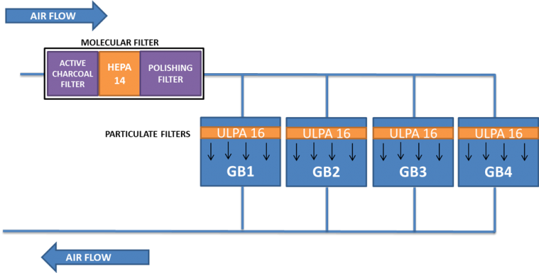
Figure 4: Schematic representation of the air flow within the isolator
The system thus allows the increasingly restrictive requirements along the line to be complied with, depending on the unidirectional process which requires the material to be inserted into GB 1, the following assembly steps in GB2 and GB 3, until complete assembly of the instrumentation in GB 4. GB4 and GB3 are in fact defined as Ultra Clean Zones.
Filtering system analysis and definition
Definition of the filter required considerable effort and it has been developed in partnership with the manufacturer Camfil. The list of AMC molecules of organic origin whose presence must be avoided inside the isolator has been directly supplied among TAS-I requirements, and during definition of the filtration system, the focus has been on substances identified as VOC (Volatile Organic Components). These VOCs are found in ambient air and, in the context of an isolator, they may be released from the plastic materials and chemicals used.
Therefore, the initial steps taken during the analysis stage were:
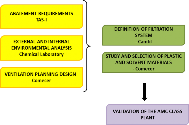
Figure 5: System definition process
- External air sampling (with specific time frames and methods) to qualitatively and quantitatively analyse input contaminants in the facility's area
- Sampling of out-gassing by the plastic material normally found in the isolator, to assess the contaminants generated within it
- Control of the operating procedures on the use of solvents and any chemical contamination generated within or in close proximity to the isolated context
For finalisation of steps 1 and 2, Comecer was supported by specialised chemical laboratories, able to identify the most effective analytical method for the purpose, and to perform sampling and subsequent analysis.
Once VOC mapping data was obtained and analysed, taking into account the ventilation system and thanks to the partnership with Camfil, it has been possible to identify and quantify the type of filtering material needed to meet and maintain the requirement.
The air changes required to maintain the ISO Class 3 cleanliness class are in each of the 4 glove boxes
This approach also enabled identification of the method of analysis to be used for validation of the filtering system upon completion and activation of the system, i.e. gas-chromatography analysis and GC-MS mass spectrometry-based on thermal desorbtion with tenax tube. The result has been the development of a canister of considerable size, containing 3 tonnes of filtering active carbon, selected and produced for the specific VOC contaminants selected, and a subsequent low out-gassing filtering stage.
Specifically, an air filtering system has been designed entailing two key components:
- Molecular filtering system upstream of the isolator's ventilation circuit, consisting of an activated carbon canister including HEPA14 absolute filtering stage with 99.995% filtering efficiency and a subsequent polishing stage.
- Particle filtration system positioned at the infeed of each of the 4 Glove Boxes, consisting of ULPA16 filters with 99.99995% filtering efficiency and featuring Ultra-Low Off-Gassing ULPA filter of molecular contaminants.
This filtering system allows the molecular contaminants and particles in the air entering the entire isolator to be immediately removed, as well as further reduction of residual particles entering individual GBs. Absolute filtration is essential to achieve ISO Class 3 as well as being an AMC-9 (or) requirement, since many of the molecular contaminants are conveyed together with the micro-particle charge.
Non-metallic materials and cleaning steps
The VOC organic molecular contaminants may be released via out-gassing (removal of inert gas from the materials), mainly by various plastic substances, lubricants and chemical solvents.
However, not all substances have the same out-gassing index: high-silicone content plastics for example release high amounts of VOC, while materials with a different chemical composition such as EPDM and FKM (Viton) show minimal out-gassing. Solvents may also release VOC – the significance of the out-gassing phenomenon varies depending on their chemical composition and concentrations of the various components.
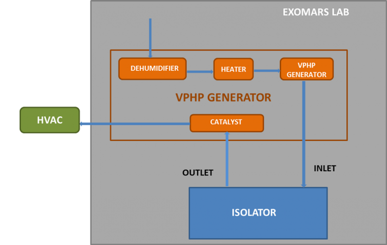
Figure 6: PHP flow in Open Loop diagram, applied to the ExoMars project
The substance release phenomenon generally diminishes over time, until it virtually disappears.
A known method to promote VOC release by the material is prolonged exposure to heat, called bake-out. By exposing the plastic materials to high temperatures for several consecutive hours, they release most of the residual volatile substances, both during and immediately post-treatment. Obviously, the thermal treatment must consider heat resistance of the material, in order to prevent its deterioration with resulting out-gassing increase.
The acceleration of VOC release induced by the treatment ensures the phenomenon then quickly decreases, until negligible.
For this reason, an in-depth analysis of these aspects was performed. The steps taken:
- Identifying all plastic components required for the system, including gloves and gaskets
- Performing out-gassing tests of the plastic material normally found in the isolator, to highlight the contaminants generated within
- Literature analysis for identifying the plastic materials with minimal impact in terms of VOC
- Research and purchase of the plastic materials with low release, such as CSM Gloves, FKM static gaskets, and metallic mechanical components with FKM gaskets
- Tests of VOC release by some plastic components
- Thermal treatment in specifically set ventilated oven, of all plastic components to speed up the out-gassing phenomenon
- Analysis of methods and stages in which solvents are normally used during processing and production of isolators
- Performing cleaning treatments of all metallic material in order to remove any solvent and oil residues used during the construction
- Analysis and implementation of a final cleaning procedure of the insides of the isolator
The final internal cleaning procedure of the isolator has been performed at Thales Alenia Space Italia, designed to minimise the use of solvents and VOC release materials. The procedure has been drawn up after an analysis of the specific project requirements and of the available literature, by the same operators who then implemented it. For this reason, only isopropyl alcohol (IPA) and low particle release cloths have been used. The procedure has been performed at the end of the installation stage.
This activity has enabled the release of VOC by the elements inside and forming the isolator to be further minimised.
Decontamination system with VPHP
For the decontamination stage of this project, great attention has also been paid to the critical aspects, essentially consisting of the molecular contamination risk and the need for absolute sterilisation. For this reason, all stages and relative components/substances used have been analysed, in order to minimise the risk of VOC release, while assuring the maximum possible level of cleanliness.
The results of integration of the various aspects analysed have led to a number of measures, including:
- Decontamination using an 'OPEN LOOP' cycle has been selected, as this method requires the air emitted by the isolator (Outlet) and charged with H2O2 residues, after being conveyed into the catalyst, to be conveyed into the isolator's ventilation system (HVAC) located outside the lab where the isolator is. The aeration stage then takes place through the HVAC, i.e. by complete extraction, speeding up the removal time of the residual H2O2, accelerating the time for reaching the TLV threshold value, and minimising the risk of the 'recycled' air conveying any pollutants.
- The instrumentation used to monitor the key parameters of the decontamination process, such as temperature, humidity, H2O2 concentration in the isolator, duration of each step of the cycle, has been calibrated and recorded each time before use.
- A hydrogen peroxide liquid solution has been selected and used, which represents the maximum standard of purity commercially available today for this purpose, indeed featuring >99.9999% purity (Hydrogen Peroxide solution, TraceSELECT Ultra, for ultratrace analysis, Fulka, Sigma Aldrich).
- The biological indicators have been identified and acquired, listed among project requirements and represented by a specific G. Stearothermophilus strain.
- Openable doors have been set at various points along the entire air distribution system to the GBT, both in the main manifold and the distributions ducts to the individual GBs, in order to assure access inside the system. Thanks to the presence of these hatches, it is possible to position both chemical and biological indicators in order to keep the effectiveness of the decontamination monitored, even in areas that are otherwise hard to reach.
- The presence of any H2O2 residues at conclusion of the decontamination and aeration cycle, has been monitored in the validation stage by means of a designated sensor featuring sensitivity equal to 0-20 ppm, to ensure successful restoration of the required initial conditions inside the isolator in terms of H2O2 residues.