
Containment in the use and handling of high potent products has several aspects that must be analysed. Containment is not absolute. The different levels of containment that can be obtained will depend on the system and technical solutions applied.
The evaluation and verification of the containment level must be in accordance with the analysis and detection capacity. The development of new and more active pharmaceutical ingredients and with lower therapeutic doses, it forces extreme containment measures and ultimately also forces the use of more sophisticated analytical detection techniques.
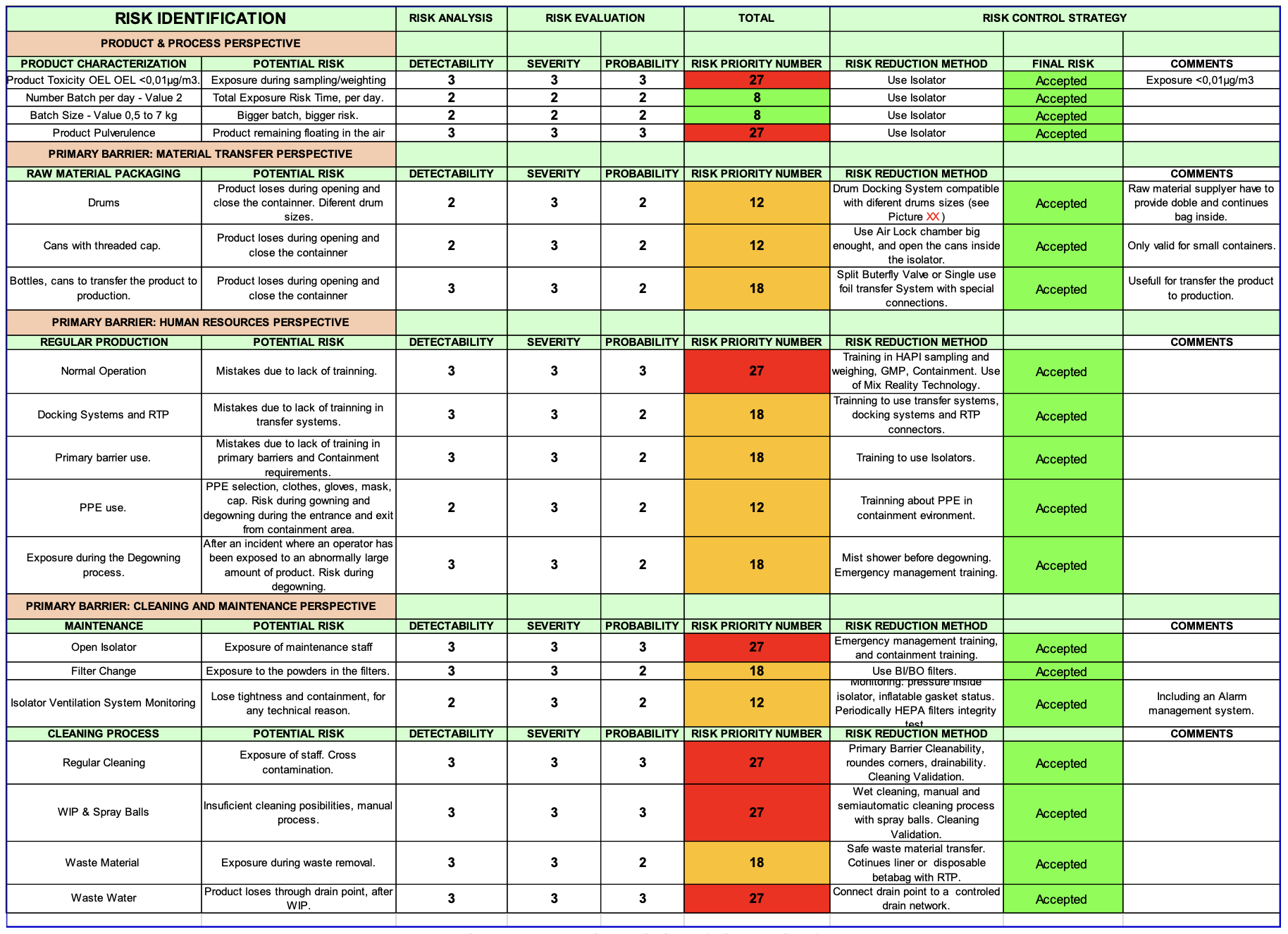
Figure 1
A drug production project with a highly potent active ingredient requires a detailed study from concept to validation. In this article we want to focus on the field of primary containment that we can achieve with a suitable design of the process under isolator. We will analyse a product weighing process.
Project phases
The phases of a project for the weighing of a high potent product require the following steps to be carried out in an orderly manner.
User requirements analysis
- Product(s) to be weighed
- Characterisation of the products
- Batch sizes to be weighed
- Number of batches per shift
- Product reception forms
- Risk analysis
- Containment strategy (open systems or closed systems: isolator)
- Conceptual design of containment equipment.
- Basic design of containment equipment.
- Detailed design of the containment equipment.
- Mock-up of the proposed solution.
- Ergonomics test.
- Material transfer tests.
- Mock-up validation.
- Equipment construction.
- FAT testing.
- Full equipment qualification.
- Containment validation (SMEPAC).
Study case - user requirements analysis
In this article we study a weighing case with the following starting data:
- API characterised as OEL <0.01µg/m3
- Product in powder form
- Source container: drum different dimensions
- Weighing batches from 0.1 to 7 kg
- Closed output format, for transfer to the process in a reactor
Risk assessment
Before initiating the risk analysis, it will be necessary to establish a basis for proper management.
It is necessary to name a person in charge, and to create a multidisciplinary team to analyse and approach the analysis from all perspectives:
In this case, the project team consists of:
- Laboratory Engineering Manager
- Laboratory Production Manager
- Laboratory Weighing Area Operator
- Laboratory HSE Manager
- Insulator Manufacturer Supplier
- Raw Material Supplier
Another important point is to determine the toxicity of the product to be handled. In many cases, a detailed characterisation of a product is not available. As there is no universal and unique system for categorising exposure control bands, pharmaceutical companies themselves often define values based on their knowledge of the product, therapeutic compounds, work environment, equipment, controls, and other factors.
A common example might be “Occupational Exposure Band 1” (OEB 1) (>1000 μg/m3), OEB 2 (10 to 1000 μg/m3), OEB 3A (1 to 10 μg/m3), OEB 3B (0.01 to 1 μg/m3), OEB 4 (<0.01 μg/m3).
Each category will have a corresponding OEL.
These categories are set based on a detailed toxicological evaluation of all possible adverse effects. The final determination of the product category does not depend on a single factor, such as the therapeutic dose. The total toxicological profile will be fixed when the category is finalised.
- Planning. Detailed planning is important, and adequate knowledge of the personnel involved and their availability is also important.
- Contents of the risk analysis: starting data and analysis, e.g. following FMEA (failure mode effects analysis)
- Communication of RISKS:
- Information distribution group
- Communication with regulatory authorities
- Review and monitoring of process risks
FMEA analysis - Containment strategy
Regarding the primary barrier, the risk analysis, and in accordance with the applicable regulations, the isolator should be selected as the containment strategy.
In this phase, the laboratory must draft the URS document, as detailed as possible, the most important aspects of the isolator from the end-user's perspective.
Conceptual design of the containment equipment
From a conceptual design point of view, we propose an isolator with the following characteristics:
- Containment isolator, with Air Lock for material entry, with two gloves for handling and main chamber with 4 gloves, with integrated weighing scale.
- Chamber and Air Lock with internal ISO 8 classification, turbulent flow, and door with inflatable seals.
- Filtration system through H-14 Push-Push filters, and double H-14 extraction filtration.
- No air recirculation.
- The isolator must be airtight according to class 3 according to ISO 14644-7.
- The isolator chamber must be welded, seamless, rounded, self-draining, and easy to clean. The internal roughness Ra<0.6.
- A weighing system must be integrated, with a weighing scale suitable for the batch size and with the scale display easily accessible by the operator inside the isolator itself.
- Manual cleaning with a spray gun in the airlock and spray balls and spray gun in the main chamber.
- Control system with HMI, allowing monitoring of the equipment and processes, with an integrated electronic data recording system validatable according to GAMP5.
- Integral alarm management system for the isolator.
- Integration with the laboratory's MES system (Figure 3).
Material inlet/outlet ports:
Inlet:
- Air Lock for entry of materials and tools. Two gloves to allow unpacking tasks.
- DRUM elevator for different sizes and sealed with inflatable gaskets during operation
Outlet:
- Split Valve Port, to metal bag or bottle.
- Waste Port, to continuous liner, with inflatable gasket seal port or RTP.
At this stage, the FDS (Functional Design Specification) document must be drafted, which covers the functional aspects of the isolator design.
Detailed design of the containment equipment
- Mechanical construction
- Material transfer systems
Inlet: Air Lock for entry of materials and tools. Two gloves to allow unpacking tasks. DRUM elevator, prepared for different sizes, and sealed with inflatable gasket seals during operation.
Outlet: Split butterfly valve port, to plastic bag or metal bottle (Figure 2).
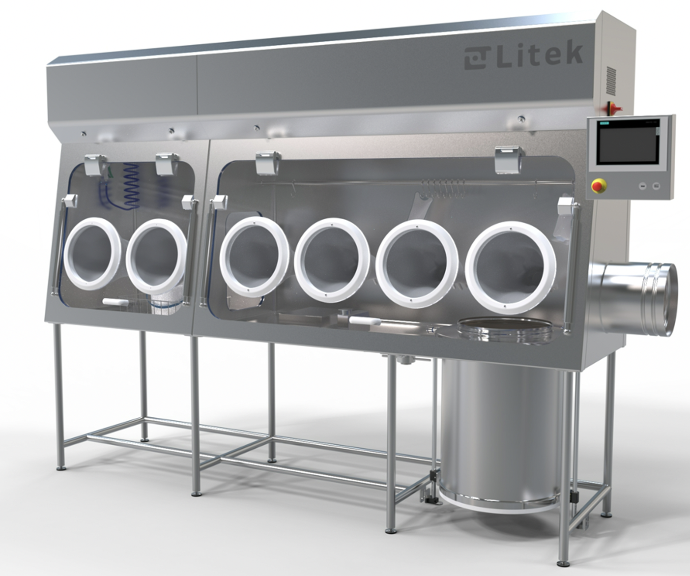
Figure 2
Waste port, a continuous liner, with inflatable seal port or RTP.
- Cleaning system
- Manual cleaning with a spray gun in the air lock, and spray balls and spray gun in the main chamber.
- The cleaning of the main chamber, where the products will be handled by the operator, will require detailed study.
- Spray balls connected to the CIP circuit will clean most of the product dispersed along the isolator.
- Control system
- The control system is based on an Industrial PLC connected to the sensors and detectors of the isolator for its correct operation.
- This software has an electronic register that can be validated according to GAMP 5.
- The control system can be integrated with the laboratory's MES system (Figure 3).
An interface solution based on mixed reality technology is integrated, where the isolator operator will have real-time access to all the necessary information for its correct use. For example, he has real-time access to the standard operating procedures, being able to review each step of the process through the mixed reality system and avoid errors during the process.
The operator himself, through the mixed reality system, will be able to inform the system of the progress of the process, having total traceability and electronic registration of the process.
- Ventilation and filtration system.
The ventilation and filtration system consists of a compact ventilation module with separate supply and exhaust EC fans. The classification obtained inside the chamber is ISO 8 according to ISO14644.
An identical system of components with the same functionalities is foreseen in both the airlock and the isolation chamber. A HEPA H-14 filtration in the supply air and a double HEPA H-14 filter in the exhaust air of both the airlock and the main chamber are foreseen.
The filters are PUSH-PUSH so that they can be changed from inside the isolator, allowing a safe filter change.
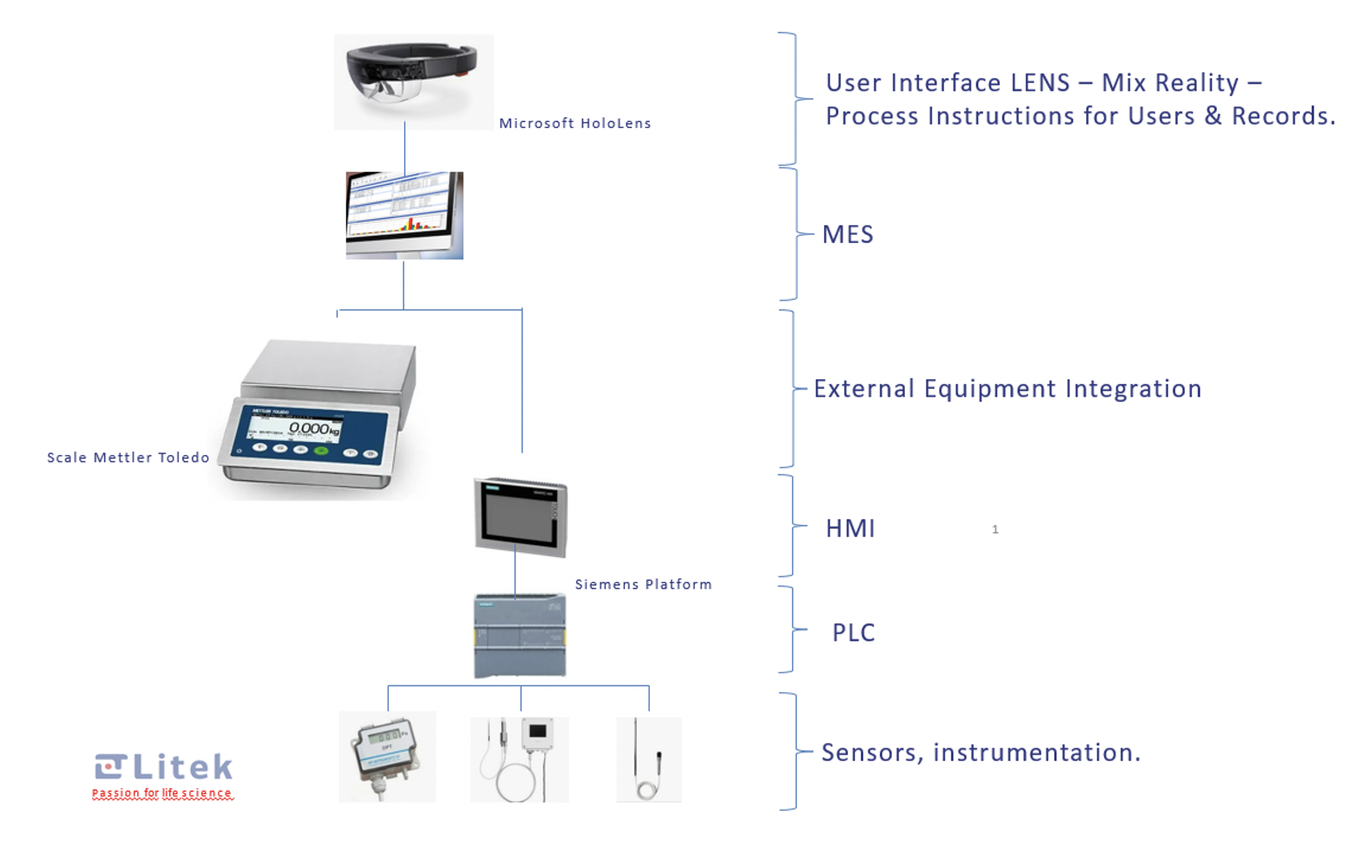
Figure 3
Mock-up of the proposed solution
The manufacture of a mock-up of the isolator in disposable material (wood or cardboard) on a scale of 1:1 is highly recommended for ergonomically studying the isolator. Hence, the user can evaluate the functionality of the isolator for the specific processes defined and it can be modified and finally approved before the construction of the definitive model in stainless steel.
It is necessary to build a multidisciplinary team to tackle the project with the highest level of knowledge and to carry out a thorough risk analysis. When it is decided to establish the isolator as the primary barrier, it will be necessary to carry out a specific project, including all the details that ensure the manufacture of a suitable isolator for the defined application, and complying with all the established requirements.