Cleanroom tightness and room pressurisation: Discrepancy?

Published: 16-Sep-2020

A cascaded room-pressure regime has been considered for decades to prevent cross-contamination of different processes. But Harald Flechl from ISPE says today's tight cleanrooms must have leaks to ensure a room-pressure regulation - so why should we build tight cleanrooms?

You need to be a subscriber to read this article.
Click here to find out more.

For preventing cross-contamination coming from adjacent areas, several guidelines refer to a positive room-pressure of about 5- 20 (10-15) Pascals (Pa) as an essential factor for airflow from higher cleanliness to a lower cleanliness graded area under static conditions. To manufacturers of pharmaceutical products and the authorities controlling them, this cascaded pressure regime and room pressurisation (see figure 1) is seen as an essential element in preventing contamination (migration of particles) from adjacent outside areas.
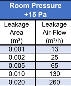
Table 1: Leakage airflow and leakage size

Table 1: Leakage airflow and leakage size

The physical fact is that room pressure depends only on the leakage-airflow volume and size of the leakage area in the room enclosure (see Table 1).

Airflow direction inside the cleanroom and supply-air and exhaust-air volume do not affect room pressure. To date, it is a misconception among QA departments and authorities that this room pressure can provide airflow to the less clean area through open doors.

The physics says absolutely no.

The door opening causes a temporary pressure impulse followed by a pressure balance of the adjacent rooms. If the door remains open the resulting airflow velocity only depends on the supply- and exhaust-air balance of these adjacent rooms.

Pressurisation and particle migration?


In the early 1950s, building the first "dust-free" production rooms created the early standards for these "cleanrooms" according to the pressurisation hvac knowledge and technical possibilities at that time.

High airflow volume through HEPA-filters (High-Efficiency Particle Air) should be able to prevent the room from high dust loads. The impermeability of the walls and ceilings was unknown and so the decision was made to have a light over-pressure which was randomly set to a value of 0.05 wg (inch of water gauge; equal to 12.5 Pa) to prevent uncontrolled migration of particles from the surrounding area.

This value was an empirical approach, without scientific reason or investigation, and should allow doors to open easily and prevent walls and ceilings from damage caused by excessive pressure on the surface.

Comparative studies and reports have shown that similar to the osmotic pressure equalisation, a migration of particles from an adjacent room with higher particle concentration can occur at 0 Pa through leaks (e.g. a door gap).

Figure 1: Overflow pressure cascading

Figure 1: Overflow pressure cascading

This osmotic migration was quantified as 0.011% of the higher level particle concentration for particle size equal to or greater than 0.5 μm. Raising the room pressure to 5 Pa nearly halved the value to 0.005%. Increasing to 10, 15 or even 20 Pa has shown no substantial change of this value. The 0.5 μm particle migration at 0 Pa from a cleanroom grade C (particle limit 3,520,000 per m3) to an adjacent cleanroom grade B (particle limit 352,000 per m3) results in a migration rate of 3 0.011% in a value of 390 per m3.

With a room 5 Pa over-pressure, this migration will be halved to approximately 200 per m3. This value is hardly measurable with commonly used laser particle counters with uncertainties of ±20% of the counted particles at this size. Comparing this migration value to the contamination by cleanroom personnel with particle disposal of up to 100,000 particles 0.5 μm shows illustrates the risk of cross- contamination by particle migration at 0 Pa is a negligible number.

It is a misconception that room pressure can provide airflow to a less clean area by flowing through open doors

The more important aspect is an effective dilution and flushing of generated particles by appropriate filtered supply air as shown in figure 2.

Determining the best location for supply-air and exhaust-air grids is essential to assure good airflow effectiveness and avoiding dead-ends with stagnating airflow and higher loaded particle concentration. This could already be supported in the design phase by computation fluid dynamic (CFD) simulation with particle-tracing to attain a well-designed room airflow.

The impact on particle dilution of the supply- air grids is much more important than the exhaust-air grids - you can blow out a candle flame but it will not work with suction. In laboratories with toxic materials, negative room pressure is required by regulatory authorities.

Figure 2: Airflow pattern in cleanrooms

Figure 2: Airflow pattern in cleanrooms

But why when the enclosure is tight?

The cleanroom status could be reached and guaranteed by efficient airflow with enforced particle migration from adjacent areas even in this case.

Room pressure in tight cleanroom enclosures

Cleanrooms with panel construction using sealed joints supply a very high degree of tightness. Provided that all wall and ceiling penetrations are correspondingly tight, the measured value of exfiltration air through leaks at a room pressure of +50 Pa (n50) will be approximately 0.2 - 0.5 of the value of the room capacity.

The German guideline VDI 2083-19 specifies grades of tightness for cleanrooms referring to the enclosure area at several pressure values. Comparing the tightness Classes 1 and 2 of VDI 2083-19 with the n50-value, results in a slightly higher leakage air rate for Class 1. A leak test carried out on a 1,000 m3 cleanroom using the Blower-Door-Test showed a leakage air rate n50 of maximum 0.5 at a pressure of +50 Pa. Consequentially, the exfiltration air volume (EXF) from the room is calculated as follows:

  • 1000 m3 x 0.5 m3.h-1.m-3 = 500 m3.h-1

According to the "Fan-Law", the EXF airflow rate at a quarter of the room pressure (12.5 Pa) is halved:

  • 50 Pa / 4 = 12.5 Pa → 500 m3.h-1/ 2 = 250 m3.h-1

The exfiltration airflow through the door-gap (1 cm at a width of 100 cm) calculated by the Bernoulli-formula for dynamic pressure at 12.5 Pa gives a value of 120 m3.h-1. The total calculated amount of exfiltration is:

  • 250 m3.h-1 + 120 m3.h-1 = 370 m3.h-1

According to the VDI 2083-19, the allowable values at the same conditions are:

  • Class 1: 580 m3.h-1
  • Class 2: 193 m3.h-1

In reverse, an infiltration air volume (INF) of approximately 370 m3.h-1 will flow into the cleanroom by reversing the room pressure to the value of -12.5 Pa. Increasing the low room pressures to 0, this volume becomes correspondingly less.

Investigations have already shown that if the ventilation systems fail and doors are open for up to 3 hours, hardly any changes in the monitoring values (particles, germs) can be detected. Even with a room pressure reversal to -20 Pa in the event of a ventilation failure, no significant influence on airborne contamination can be detected for up to 1.5 hours.

Does room pressure need to be regulated?

A cleanroom is a self-contained, not completely sealed but constant system. This implies that there is no change in the room itself or the containment (leaks). The opening of doors is to be excluded here as it does not represent a disturbance variable and is also defined in the pharmaceutical guidelines: "The room pressure should be achieved under static conditions with doors closed."

With active room pressure control (e.g. by a Building Management System, BMS), to keep the room at an almost constant value, the pressure drop in the exhaust air-duct will be increased by adjustable variable airflow valves (VAV) until the desired room pressure is achieved.

Table 1 shows a significant correlation: the smaller the leakage area, the smaller the necessary exfiltration airflow to keep the specified room pressure. But the smaller the airflow, the more difficult it is for the BMS and the VAV to hold a constant value. BMS and VAV manufacturers see a required lower limit of about 10% of the supply airflow to assure the operation of the room pressure regulation, but this is contrary to the requirement of a tight cleanroom enclosure.

Figure 3: Volume flow vs dp pressurisation hvac

Figure 3: Volume flow vs dp pressurisation hvac

It is not only the response time, but also the control tolerance, which is usually ±3-5% of the nominal volume flow of the control element, that have a significant influence on a constant room pressure. Let's see the example of a cleanroom of 1000 m3 described before with supply/exhaust airflow of 10000 m3.h-1, meaning an air change per hour (ACPH) of 10 (usually the ACPH rate in a grade C cleanroom is about 20).

The control tolerance of the VAV at 3% is ±300 m3.h-1 resulting in a total tolerance of 600 m3.h-1. With this value of tolerance, it is not possible to exactly regulate an airflow volume of 380 m3.h-1, which represents the exfiltration airflow volume of the "tight enclosure" of this cleanroom, particularly this exfiltration volume does not change - "constant system cleanroom".

From a technical point of view, tight construction is preferable to room pressure regulation

Exceptions are only given by variable or on/off exhaust airflow caused by fume hoods or similar, which of course have to be balanced by the BMS. Thus leading to paradoxical solutions, where a tight enclosure of a cleanroom is fitted with additional cutouts or enlarged door-gaps to increase the exfiltration airflow volume above the tolerance level of the BMS/VAV to achieve the operation of the room pressure regulation (see figure 3).

Tight containment or regulated room pressure?

Tight cleanroom containment and the active regulation of a constant room pressure are contradictory. The influence of room overpressure on possible contamination by infiltration is hardly a given with the tight cleanroom construction of today.

Nevertheless, for 60 years it has been considered important and required in the various guidelines for the industry –and thus also by the inspectors– for the prevention of cross-contamination in controlled environments.

Particle dilution with supply-air grids is more important than exhaust ones - you can blow out a candle but it will not work if you suck

A tight cleanroom under constant conditions with good ventilation efficiency and optimised airflow has a much higher influence on the prevention of airborne cross-contamination and does not require room pressure, therefore it is not necessary to regulate the room pressure.

Door opening equalises the room differential pressure and also is impossible to be compensated by a much higher overpressure, just as room overpressure does not influence contamination by material and personnel flow. The effect of a change or even overlap of an existing room pressure cascade from the calculations shown above should therefore not be overrated and should also be outlined accordingly in the risk assessment.

The design values and the permitted tolerances for alarms and actions have to be defined accordingly. Therefore, for newly built production cleanrooms the choice should be either tight construction or leakage with room pressurisation cascades.

In case of failure, break-down or planned shutdowns (energy saving!) of the ventilation system, the tight construction of the cleanroom has the advantage to avoid migration of contaminants.

From a technical point of view, the tight construction is preferable to the room-pressure cascading or room-pressure regulation.

You may also like