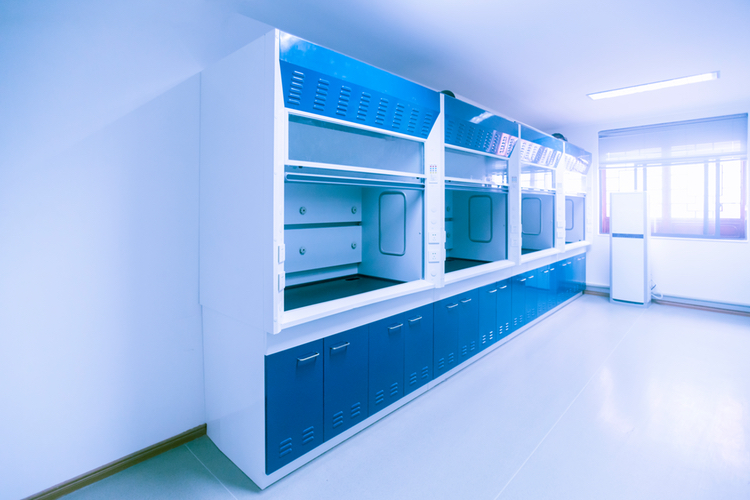
Fume hoods are both a protective and control device fitted in laboratories where chemicals are used. They are a conventional fume extraction unit designed so that airborne contaminants are contained in the enclosure prevented from entering the room or laboratory by means of a protective air barrier between the user and the materials placed within the equipment.
Performance testing is essential to confirm that the fume hood is operating to a level to provide the desired arrest, containment and removal of the fume.
The tests are based on ANSI/ASHRAE Standard 110, Method of Testing Performance of Laboratory Fume Hoods. When the hood is already operational in the laboratory, it is recommended to test in two operating conditions: as installed and as used.
For the "as installed" test, the laboratory hood is installed at the customer's location and tested empty, but with the ventilation system in the installation balanced and the hood in its final location. For the "as used" test, the assessment is conducted after the hood has been installed and used by the chemist. The equipment and tools remain in the hood and other activities in the laboratory continue.
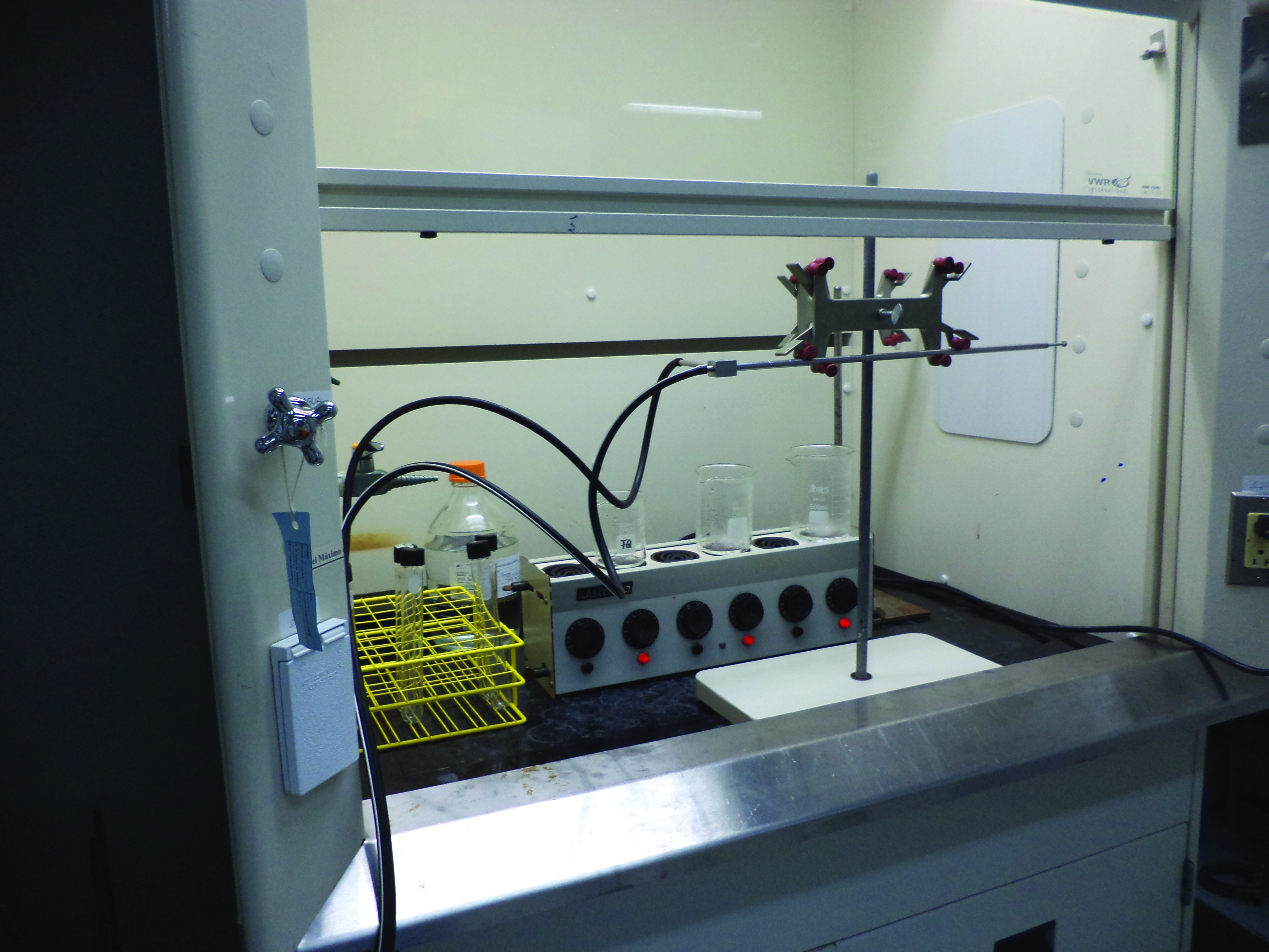
Figure 1: Velocity test with the hood in operational condition “as used”
Airflow face velocity test
The purpose of this test is to validate that the average airflow face velocity meets the specified requirements at the required sash configuration.
An adequate face velocity is necessary but is not the only criterion to achieve acceptable performance and should not be used as the only performance indicator.


