Cleanroom Gas Sampling Using a Particle Counter
GMP requires you test compressed gases in cleanroom applications. This testing is critical because product process zones in ISO 5 cleanrooms require tight contamination control. Compressed gases, if not correctly properly checked, can be an avenue for particle contamination. This can impact the quality and safety of sterile products. Testing gas lines mitigates against adding another source of cleanroom contamination that may impact the cleanroom’s set classification based on operating conditions.
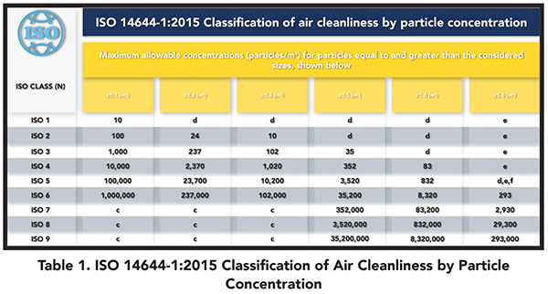
ISO 14644-1 states the required air cleanliness for different classes of cleanrooms based on a cubic meter sample of air taken at given locations. The result is compared to a table, which validates the cleanroom ISO class. For example, ISO 14644-1 requires a cleanroom to have the following limits per cubic meter of air sampled.

In the pharmaceutical industry, sterile processing mainly occurs in cleanrooms with an ISO 5 classification. Therefore, the particle concentration should be below the limits for the sizes tested. If 0.5μm and 1.0μm particles were tested using a particle counter, then the limit for each size would be 3,520 and 832, respectively, per location.
The number of locations is based on a lookup table (outlined in ISO 14644-1:2015) and the size of the cleanroom. If all sample locations are below the particle sizes per cubic meter at each sample, then the cleanroom would be classified as an ISO 5 cleanroom.
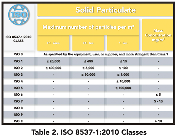
If there was a contaminated gas line, there is potential for the introduction of the gas to contaminate the room further and potentially fail the ISO 5 classification. This could lead to a risk of product safety and quality. ISO 8573 is a standard to follow when testing gas lines. There are several parts to ISO 8573, but parts 4 and 7 refer to particulate contamination. ISO 8573-1:2010 outlines the maximum number of particulates per m3 which is the same concept as ISO 14644-1:2015.
ISO 8573 – Part 4:
1. Provides a method for sampling compressed air.
2. A guide for choosing suitable measuring equipment to determine its particle size and
concentration by number.
3. Establishes a minimum sampling volume of 1000L (1m3).
4. Use of Optical Particle Counter for testing sizes from ≥ 0.1 to ≤ 10μm.

ISO 8573-1: 2010 Table for Solid Particle Classes
For example, a Class 5 cleanroom with particle diameter 0.5 < d ≤ 5.0μm would have an expected maximum number of particles per m3 sample less than 100,000. For Class 4, that value would be ≤10,000. Class 3 would be ≤1000, Class 2 would be ≤100, and Class10 would be ≤10.
Using an Optical Particle Counter (ISO 8573-4)
- Isokinetic sampling should be maintained (If particle diameter is > 1μm, use High Pressure Diffuser)
- OPC Particle size range 0.1μm to 5μm
- Sample Report to include;
- Sterile or non-sterile statement
- Date of sampling
- Date of measurements
- Location
Choosing The Right HPD
To sample compressed gas, a particle counter will need an accessory called a High Pressure Diffuser (HPD). The HPD connects the particle counter and the compressed gas line and diffuses the gas as is enters the particle counter sample inlet. If the high-pressured gas enters the particle counter sample inlet without the HPD, the sensor inside the particle counter can be damaged and the results of the testing will not be accurate.
There are two types of HDPs offered by Lighthouse Worldwide Solutions: Vented Return HPD and Ported Exhaust HPD. Vented Return HPD vents the gas into the environment and is best suited for gases such as air. If the gas should not be in the environment, you should use a Ported Exhaust HPD, which will safely vent the gas outside the environment.
Setting Up The HPD Flow Rate
When using an HPD, it is critical to match the flow rate of the particle counter used to test the compressed gas.
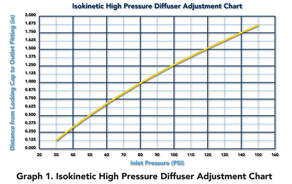
Depending on the HDP and particle counter model, setting the proper airflow is necessary in order to verify the system is setup correctly and the results are as accurate as they can be based on iso-kinetic sampling. Iso-kinetic sampling maintains the correct airstream and, with the right pressure, enables the particle counter to sustain the right flow rate as the flow rate is critical to the accuracy of the sample results. The table below outlines the correct HPD adaptor adjustment based on the inlet pressure of the compressed gas to be sampled to maintain ideal flow into the particle counter for accurate sampling.

Setting Up The Particle Counter and HPD For Compressed Air Sampling
The HPD connects between the compressed gas line and the particle counter based on the diagram below. Take care to ensure the adaptor fittings are tight, the gas line is free from any leakage, and the air is flowing in the correct direction.
With the correct set-up and team on your side, the process is seamless and smooth. Particle counters should be powerful, multi-use tools and the Lighthouse team is dedicated to ensuring you get the most out of your particle counter as possible. When working with one of our particle counters, such as the ApexZ50, our team will stand alongside you to ensure proper training and maximisation of the application.

